
The Complete Guide to Reading Construction Drawings for Beginners
- Anjali Regmi
- Jun 7
- 7 min read

Construction drawings, often referred to as blueprints, are the universal language of the construction industry. They communicate the design, dimensions, materials, and construction requirements of a project to architects, engineers, contractors, supervisors, and workers.
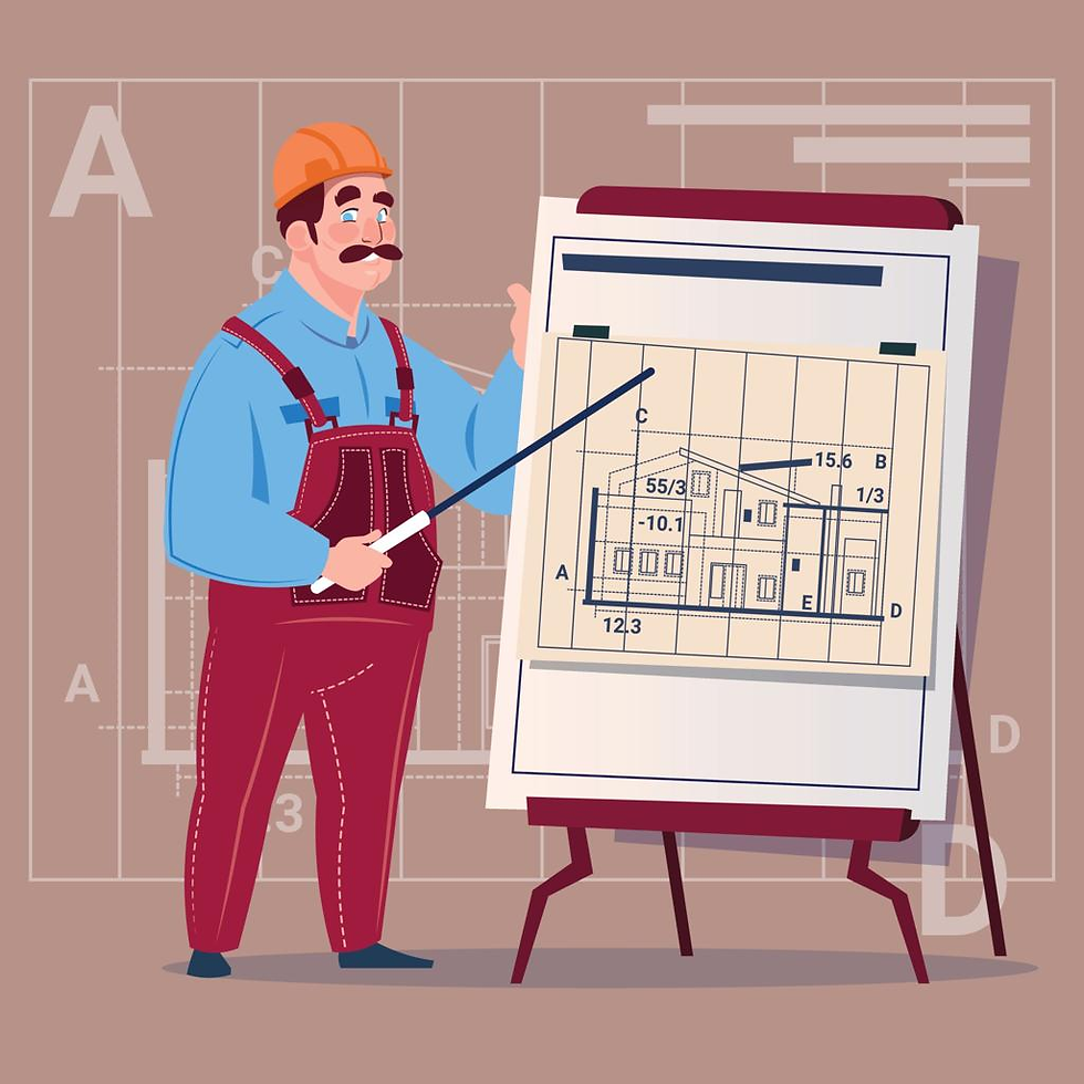
Whether you are a civil engineering student, a site engineer, an architect, or simply someone interested in understanding how buildings are constructed, learning to read construction drawings is an essential skill.
At first glance, construction drawings may appear complex due to the large number of lines, symbols, abbreviations, dimensions, and technical details. However, once you understand the basics and learn how different drawings relate to one another, interpreting them becomes much easier. This guide will provide a detailed introduction to construction drawings and help beginners develop the confidence to read and understand them effectively.
What Are Construction Drawings?
Construction drawings are technical documents that visually represent a building or infrastructure project. They provide detailed information regarding the design, layout, dimensions, materials, and construction methods required for a project.
These drawings serve multiple purposes:
Communicating design intent
Obtaining project approvals and permits
Guiding construction activities
Coordinating work among different disciplines
Estimating costs and quantities
Ensuring quality and compliance
Without accurate construction drawings, executing a project efficiently and safely would be nearly impossible.
Why Construction Drawings Are Important
Construction drawings act as the primary reference throughout the construction process. Every professional involved in a project depends on these drawings for information.
For Architects
Architects use drawings to communicate their design concepts, layouts, aesthetics, and space planning.
For Engineers
Structural, electrical, mechanical, and plumbing engineers rely on drawings to integrate their systems into the project.
For Contractors
Contractors use drawings to understand project requirements, plan resources, and execute construction activities.
For Site Supervisors
Site supervisors compare ongoing work with drawings to ensure construction follows the approved design.
For Clients
Clients can visualize the final project and verify that their requirements have been incorporated.
Components of a Construction Drawing Set
A complete drawing set usually contains several sheets covering different aspects of the project. Understanding each sheet's purpose is the first step toward reading drawings effectively.
Cover Sheet
The cover sheet provides an overview of the project and typically includes:
Project name
Project location
Drawing index
Consultant information
Revision history
General notes
Before reviewing any drawing set, always start with the cover sheet.
Site Plan
The site plan shows the entire project in relation to the surrounding area.
It includes:
Property boundaries
Building location
Roads and pathways
Parking areas
Landscaping
Utility connections
North direction
The site plan helps viewers understand how the structure fits within the available land.
Architectural Drawings
Architectural drawings focus on the building's appearance and layout.
Common architectural drawings include:
Floor Plans
A floor plan is a horizontal cut through a building viewed from above.
It shows:
Room layouts
Doors
Windows
Walls
Staircases
Furniture layouts
Floor plans are among the most frequently used construction drawings.
Elevations
Elevations show the exterior faces of a building.
They display:
Building height
Architectural finishes
Window placements
Door positions
Roof features
Typical elevation drawings include:
Front elevation
Rear elevation
Left-side elevation
Right-side elevation
Sections
Sections are vertical cuts through a structure.
They reveal:
Internal construction details
Floor-to-floor heights
Foundation arrangements
Roof construction
Wall assemblies
Sections provide information that cannot be understood from floor plans alone.
Detailed Drawings
These drawings enlarge specific areas for clarity.
Examples include:
Stair details
Door details
Window details
Toilet layouts
Kitchen layouts
They provide exact construction instructions.
Structural Drawings
Structural drawings describe how a building will safely support loads.
Prepared by structural engineers, these drawings include:
Foundation Plans
Foundation plans show:
Footings
Foundation walls
Column locations
Excavation details
These drawings guide the construction of the building's base.
Column Layouts
Column drawings specify:
Column dimensions
Reinforcement details
Column locations
Identification numbers
Every structural column is uniquely marked.
Beam Layouts
Beam drawings indicate:
Beam positions
Sizes
Reinforcement requirements
Connections
Beams transfer loads from slabs to columns.
Slab Drawings
Slab drawings provide:
Thickness
Reinforcement arrangement
Openings
Levels
These drawings are critical for reinforced concrete structures.
Mechanical, Electrical, and Plumbing (MEP) Drawings
Modern buildings require various services that are represented through MEP drawings.
Mechanical Drawings
Mechanical drawings show:
HVAC systems
Air ducts
Ventilation systems
Equipment locations
These ensure comfortable indoor conditions.
Electrical Drawings
Electrical drawings indicate:
Lighting fixtures
Power outlets
Switchboards
Cable routes
Earthing systems
Electricians rely heavily on these drawings during installation.
Plumbing Drawings
Plumbing drawings include:
Water supply lines
Drainage systems
Sanitary fixtures
Pipe sizes
These ensure proper water distribution and waste disposal.

Understanding Drawing Scales
Construction drawings are produced at reduced sizes using scales.
A scale represents the relationship between the drawing and actual dimensions.
For example:
Scale 1:100 means 1 unit on the drawing equals 100 units in reality.
Scale 1:50 means 1 unit on the drawing equals 50 units in reality.
Common scales include:
Drawing Type | Typical Scale |
Site Plan | 1:500 |
Floor Plan | 1:100 |
Elevation | 1:100 |
Sections | 1:50 |
Details | 1:10 or 1:20 |
Always check the drawing scale before taking measurements.
Reading Drawing Title Blocks
The title block contains essential project information and is usually located at the bottom-right corner.
A title block typically includes:
Project title
Drawing title
Drawing number
Scale
Date
Revision number
Consultant details
Approval signatures
For example:
A101 = Architectural Floor Plan
S201 = Structural Drawing
E301 = Electrical Drawing
Understanding drawing numbers helps you locate related sheets quickly.
Understanding Drawing Symbols
Construction drawings use symbols to represent objects and components.
Door Symbols
Doors are usually shown as arcs indicating the direction of opening.
Window Symbols
Windows are represented by breaks within walls.
Column Symbols
Columns appear as rectangles, squares, or circles depending on shape.
Electrical Symbols
Electrical drawings contain symbols for:
Lights
Fans
Switches
Sockets
Distribution boards
Plumbing Symbols
Plumbing drawings use symbols for:
Wash basins
Water closets
Showers
Pipes
Each drawing set typically contains a legend explaining all symbols used.
Understanding Construction Abbreviations
Construction drawings use abbreviations to save space.
Common examples include:
Abbreviation | Meaning |
CL | Center Line |
FFL | Finished Floor Level |
NGL | Natural Ground Level |
RCC | Reinforced Cement Concrete |
TYP | Typical |
EQ | Equal |
Ø | Diameter |
BOT | Bottom |
TOP | Top |
C/C | Center to Center |
Learning these abbreviations significantly improves drawing interpretation.
Understanding Dimensions
Dimensions indicate exact measurements and are among the most important elements of construction drawings.
Dimensions may be shown in:
Millimeters (mm)
Centimeters (cm)
Meters (m)
Inches
Feet
For example:
3000 mm = 3 meters
A room dimension shown as 4000 × 5000 means the room is 4 m by 5 m.
Always rely on written dimensions rather than scaling directly from drawings.
Grid Lines and Reference Systems
Most large buildings use grid systems.
Grid lines help locate structural elements accurately.
Typically:
Horizontal grids use numbers (1, 2, 3, 4)
Vertical grids use letters (A, B, C, D)
A column located at Grid B-3 means it lies at the intersection of grid line B and grid line 3.
Grid systems improve communication and reduce errors.
Reading Levels and Elevations
Construction drawings use levels to indicate vertical positions.
Examples include:
Ground Level (GL)
Finished Floor Level (FFL)
Plinth Level (PL)
Roof Level (RL)
A notation such as:
FFL +0.000
indicates the project's reference level.
A level marked:
+3.600
means it is 3.6 meters above the reference point.
Understanding levels is essential for accurate construction.
Interpreting Section Marks
Section marks indicate where a building has been cut vertically.
A section symbol usually contains:
Section number
Drawing number
For example:
Section A-A
This means you should locate the corresponding section drawing to understand the building's internal construction.
Reading Detail References
Complex areas often require detailed drawings.
You may encounter notes such as:
"Refer Detail 5/S302"
This means:
Detail Number = 5
Drawing Sheet = S302
Always follow these references for complete information.
Understanding Revisions
Construction drawings frequently undergo revisions.
Each revision is recorded in the revision block.
Revision information may include:
Revision number
Date
Description of changes
Examples:
Rev A
Rev B
Rev C
Using outdated drawings can result in costly construction mistakes.
Always ensure you are working with the latest revision.
Step-by-Step Method to Read Construction Drawings
Beginners often feel overwhelmed when viewing large drawing sets. Following a systematic approach makes the process easier.
Step 1: Review the Cover Sheet
Understand:
Project scope
Drawing index
Consultant details
Step 2: Study the Site Plan
Identify:
Property boundaries
Building location
Access roads
Step 3: Examine Floor Plans
Understand:
Room arrangements
Door and window locations
Circulation paths
Step 4: Review Elevations
Observe:
Building appearance
Heights
Exterior finishes
Step 5: Analyze Sections
Understand:
Internal structure
Floor levels
Roof details
Step 6: Study Structural Drawings
Review:
Foundations
Columns
Beams
Slabs
Step 7: Check MEP Drawings
Understand:
Electrical systems
Plumbing systems
HVAC arrangements
Step 8: Cross-Reference Information
Compare all drawings to gain a complete understanding of the project.
Common Mistakes Beginners Make
Many beginners struggle due to avoidable errors.
Ignoring Scales
Always verify the drawing scale.
Not Checking Revisions
Using old drawings can create major site problems.
Overlooking Notes
General notes often contain critical construction instructions.
Ignoring Sections
Floor plans alone do not provide complete information.
Misreading Symbols
Always consult the drawing legend.
Failing to Cross-Reference
Construction drawings must be read together, not individually.
Tips for Improving Drawing Reading Skills
Practice Daily
Review real construction drawings regularly.
Learn Industry Symbols
Familiarity with symbols speeds up interpretation.
Visit Construction Sites
Comparing actual construction with drawings improves understanding significantly.
Study Building Components
Learn how foundations, columns, beams, slabs, and walls work together.
Ask Questions
Experienced engineers and supervisors can explain practical drawing applications.
Use CAD Software
Programs such as AutoCAD help visualize construction drawings more effectively.
Conclusion
Reading construction drawings is one of the most valuable skills for anyone entering the construction and civil engineering industry. Although drawings may initially seem intimidating, they become much easier to understand when approached systematically. By learning drawing types, scales, symbols, dimensions, sections, elevations, and structural details, beginners can gradually develop the ability to interpret even complex projects confidently.

Construction drawings are more than technical documents—they are the roadmap that transforms an idea into a physical structure. The more time you spend studying them, the better you will understand how buildings are designed, coordinated, and constructed. With regular practice and exposure to real-world projects, reading construction drawings will eventually become second nature, laying a strong foundation for a successful career in construction, civil engineering, architecture, or project management.ā


Comments