
Reading Structural Drawings Like a Pro: A Site Engineer’s Practical Guide to Avoid Costly Errors
- Anjali Regmi
- Feb 26
- 4 min read

In real construction projects, structural drawings are the single most critical technical documents that guide site execution. Yet, one of the most common reasons for rework, structural defects, and cost overruns is the misinterpretation of drawings on site. Many civil engineers, especially freshers, understand theoretical design concepts but struggle when translating complex structural drawings into actual construction work. The gap between design intent and site execution often leads to reinforcement errors, dimensional inaccuracies, and structural inconsistencies that can severely impact project quality and safety.
Mastering the skill of reading structural drawings is not just a technical requirement but an operational necessity for site engineers responsible for accurate and efficient execution.
Understanding the Role of Structural Drawings in Site Execution
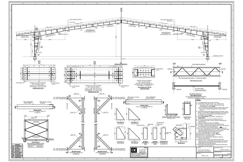
Structural drawings provide detailed information about dimensions, reinforcement detailing, load-bearing elements, and construction specifications. These drawings include plans, sections, elevations, and detailed reinforcement layouts that ensure the structure is built exactly as per design standards. Unlike architectural drawings that focus on aesthetics and layout, structural drawings emphasize safety, stability, and load distribution.
A site engineer who fails to properly interpret these drawings risks executing incorrect reinforcement placement, improper beam depths, or inaccurate column alignment, which can lead to structural weakness and costly demolition or redesign.
Key Components of Structural Drawings Every Site Engineer Must Decode
1. General Notes and Specifications
The first and most ignored section in structural drawings is the general notes. These notes contain crucial technical instructions related to concrete grade, steel grade, cover requirements, and design codes. Ignoring general notes often leads to incorrect material usage and non-compliance with design specifications.
2. Plan, Section, and Elevation Views
Plan views show the top layout of structural elements like beams, columns, and slabs. Section views provide cross-sectional details such as depth, reinforcement spacing, and layering. Elevations indicate vertical alignment and structural height details. Engineers must correlate all three views to understand the complete structural behavior rather than relying on a single drawing sheet.
3. Reinforcement Detailing and Bar Marking
Reinforcement drawings include bar diameters, spacing, lap lengths, anchorage details, and bending shapes. Misreading bar marks or ignoring lap length specifications can compromise structural strength and load distribution. This is particularly critical in beams, columns, and footing reinforcements where precision is non-negotiable.
Common Drawing Interpretation Mistakes on Construction Sites
Misreading Scale and Dimensions
One of the most frequent site errors is incorrect measurement due to misunderstanding drawing scales. Engineers who rely solely on visual estimation instead of scaled dimensions risk dimensional deviations that affect structural alignment and finishing works.
Ignoring Revision Clouds and Updated Drawings
Construction drawings are frequently revised during project execution. If site engineers fail to check revision numbers or updated sheets, outdated drawings may be used for execution. This results in rework, material wastage, and project delays.

Overlooking Reinforcement Cover and Spacing
Concrete cover and bar spacing are essential for durability and corrosion resistance. Misinterpretation of these details leads to inadequate cover, exposing reinforcement to environmental damage and reducing structural lifespan.
How Drawing Misinterpretation Leads to Costly Construction Errors
When structural drawings are not properly understood, execution errors occur at multiple stages. Incorrect footing dimensions can cause foundation instability, while improper beam reinforcement can lead to deflection and cracks. In slab construction, misunderstanding thickness and reinforcement direction may result in structural failure under load. These mistakes not only affect safety but also increase project costs due to rework, redesign, and legal implications.
Practical Approach to Reading Structural Drawings on Site
Step 1: Cross-Verify Architectural and Structural Drawings
Site engineers must always compare architectural and structural drawings to identify discrepancies. Differences in column positions, slab openings, or beam layouts should be clarified before execution to avoid structural conflicts.
Step 2: Study Bar Bending Schedule (BBS) Alongside Drawings
The Bar Bending Schedule provides detailed information on cutting length, bending shapes, and steel quantity. Reading BBS in coordination with reinforcement drawings ensures accurate steel placement and minimizes wastage.
Step 3: Conduct Pre-Execution Drawing Briefings
Before starting any major activity like footing, slab, or column casting, engineers should conduct toolbox briefings with supervisors and contractors. Explaining drawings to the site team ensures alignment and reduces execution errors.

Operational Challenges Faced by Site Engineers While Interpreting Drawings
Real construction environments present challenges such as incomplete drawings, last-minute design changes, and coordination gaps between consultants and contractors. Engineers often work under time pressure, making quick decisions that may lead to oversight. Additionally, complex reinforcement details in high-rise or infrastructure projects require advanced technical understanding and on-site clarification from structural consultants.
Language barriers with labor teams and lack of technical training among workers further complicate execution based on drawings. This makes the engineer’s role as a technical communicator extremely important.
Digital Tools and Modern Methods for Better Drawing Interpretation
With the advancement of construction technology, engineers now use software like AutoCAD, BIM (Building Information Modeling), and digital drawing viewers to interpret structural designs more efficiently. BIM models provide 3D visualization of structural components, helping engineers detect clashes and understand complex reinforcement arrangements before execution.
Mobile-based drawing management tools also allow real-time access to updated drawings, reducing the risk of using outdated documents on site.
Quality Control and Inspection Based on Structural Drawings
Structural drawings serve as the reference point for quality inspections. Engineers must verify reinforcement placement, shuttering dimensions, and structural alignment according to drawing specifications before concreting. Inspection checklists based on drawings help maintain accuracy and compliance with engineering standards.
Regular site audits and joint inspections with consultants further ensure that execution aligns with design intent and structural safety requirements.
Conclusion: Drawing Literacy is a Core Skill for Civil Engineering Excellence
Reading structural drawings like a professional is one of the most underrated yet powerful skills in civil engineering operations. Most on-site failures, rework costs, and structural defects originate from drawing misinterpretation rather than design flaws. A technically sound site engineer who can accurately decode drawings, coordinate with teams, and execute work as per specifications significantly enhances project efficiency and structural reliability.
In today’s fast-paced construction industry, engineers who master drawing interpretation gain a competitive edge by minimizing errors, reducing rework, and ensuring precise execution. Ultimately, the ability to translate complex structural drawings into flawless on-site execution defines the difference between an average engineer and a highly competent construction professional.


Comments